3D-print a geological ground model: one watertight STL per stratum
Turn the kriged stratum surfaces from Part 5 into a multi-material 3D print of the Cotswold escarpment at Crickley Hill. Cut a window, decide what is too thin to print, build one solid per unit with mesh booleans, prove the parts fit exactly and are watertight, and write five STLs and a colour 3MF for AMS and MMU printers.
- Level
- Advanced
- Tested with
- Python 3.12
- Source code
- Download scripts
Key takeaways
- Build one solid per unit from the stratum surfaces: a heightfield solid from the plinth up to each surface, then subtract the one below. Subtract first and trim to the footprint second, or the shared side walls leave needle-thin triangles on the outside.
- Decide what is too thin to print in millimetres, not metres. At 1:9,450 with three times vertical exaggeration, 0.6 mm is 1.89 m of strata: about half the superficial deposits' area is handed to the unit below, and the thick head and landslide deposits stay.
- Prove the print before you write it: every part watertight and consistently oriented, the parts adding up to the ground solid to within 0.0000%, and no volume shared between any two parts.
- Render the previews from the STL files read back from disk, so the pictures show exactly what the slicer will get.
Before you start
- Part 5 of this series run first: this script reads its output/model/ surfaces
- Python 3.10+ with numpy, rasterio, shapely, scipy, manifold3d, pyvista and matplotlib
- A multi-material printer (Bambu Lab AMS, Prusa MMU or similar) for the colour print, or filament changes on a single extruder
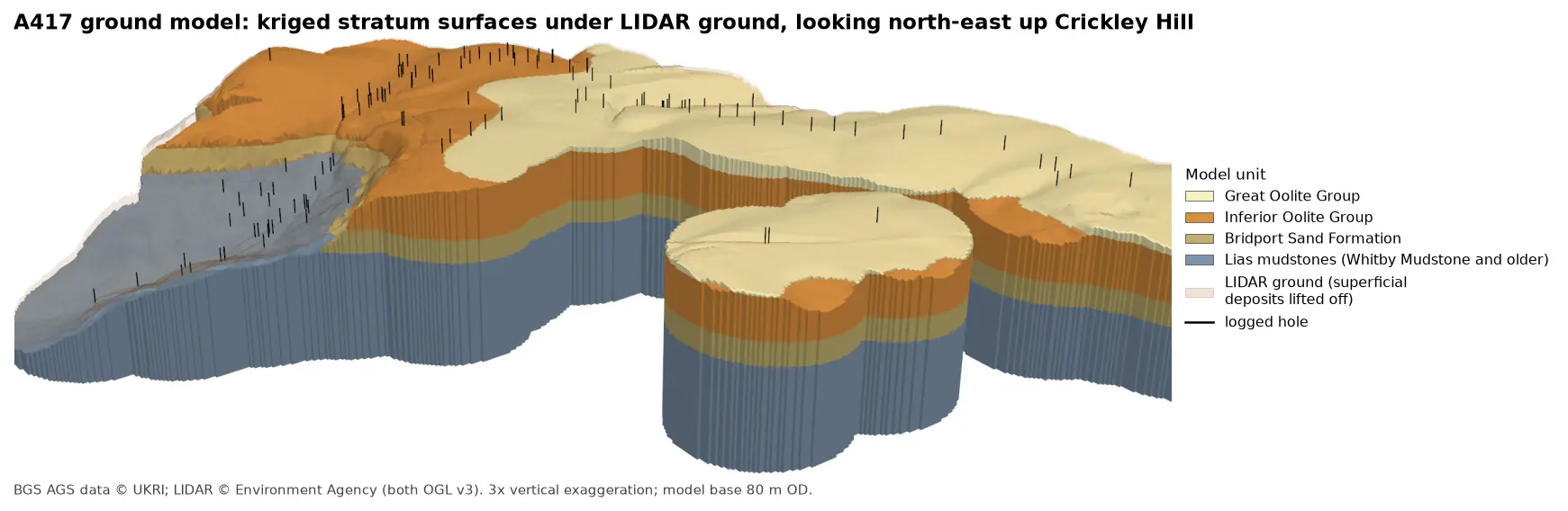
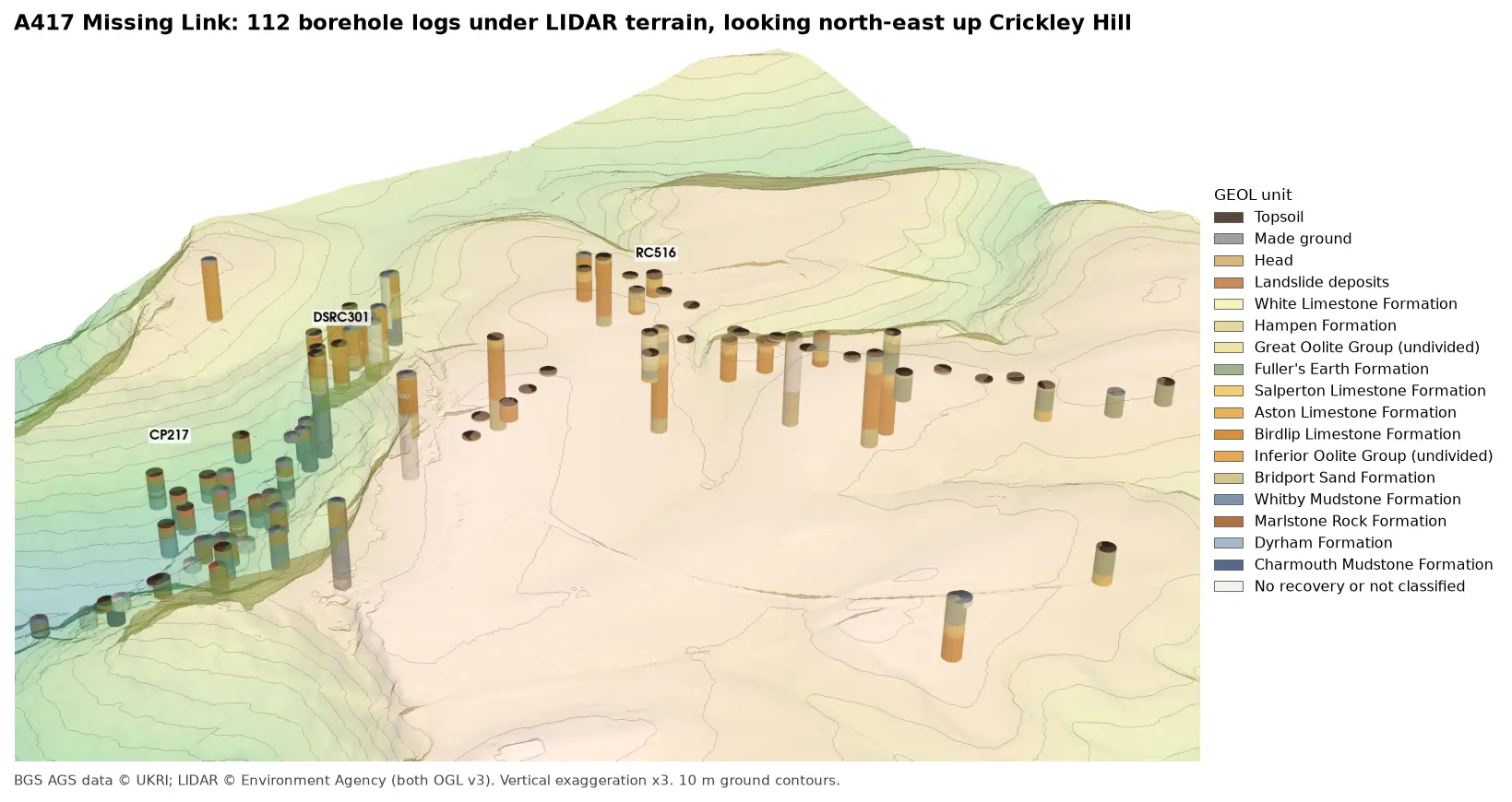
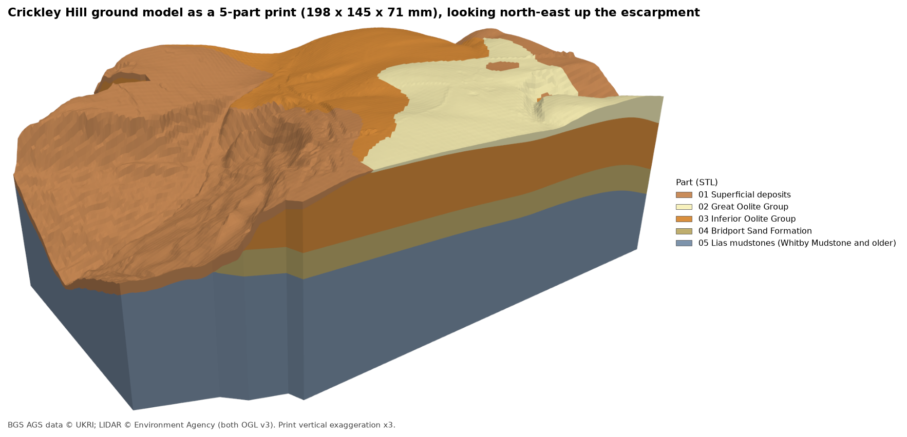
A ground model you can hold in your hand explains a site faster than any section. In Part 5 we kriged the A417 boreholes into a stack of stratum surfaces under the LIDAR ground, and tested them. Now we print them: a 20 cm block of the Cotswold escarpment at Crickley Hill, with the superficial deposits, Great Oolite, Inferior Oolite, Bridport Sand and Lias each printed as a separate part in its own colour.
The approach is the one from the 3D-printed maps with Python series: build one watertight solid per colour with mesh booleans, check every part, and write STLs and a 3MF. What is new is that the colours are not drawn on the surface; they are the geology, and they go all the way through. Cut the print in half and you see the section.
The steps are:
- read the stratum surfaces in the print window;
- trace the footprint of the model;
- convert to print heights, and decide what is too thin to print;
- build one solid per unit;
- check every part before writing;
- write one STL per unit and a colour 3MF;
- render the previews from the STL files.
The code is print_ground_model.py. It reads output/model/ from Part 5 and runs in about seven seconds.
Step 1: the stratum surfaces in the print window
Part 5 wrote each surface as a GeoTIFF on the same 10 m grid, plus a model.json listing the units from the top down. The top of each unit is the base of the one above, and the bottom unit runs down to a flat model base at 80 m OD. The script checks that before it reads anything, so a change to Part 5 that broke the stack would stop here, not in the slicer.
meta = json.loads((args.model / "model.json").read_text(encoding="utf-8"))units, base_m = meta["units"], float(meta["model_base_mOD"])for upper, lower in zip(units, units[1:]):    assert upper["base"] == lower["top"], f"{upper['code']} base and {lower['code']} top must be the same surface"assert units[-1]["base"] is None, "the bottom unit runs down to the flat model base"
grids = []for u in units:    with rasterio.open(args.model / f"{u['top']}.tif") as src:        win = from_bounds(*WINDOW, transform=src.transform).round_offsets().round_lengths()        win = win.intersection(Window(0, 0, src.width, src.height))        grids.append(src.read(1, window=win).astype("float64"))        res, wt = src.res[0], src.window_transform(win)S = np.stack(grids)                                   # (surface, row, col), top surface firstvalid = np.isfinite(S).all(axis=0)
The window, 1.9 by 1.4 km, takes in the scarp face, the plateau and the vale below, where the boreholes are densest. Part 5 only modelled ground within 300 m of a logged hole, so the model covers 89.6% of the window.
Part 5 already made sure the surfaces never cross, but a print is unforgiving, so the script applies the rule again (np.minimum.accumulate down the stack) and counts how many cells it had to change. None did:
=== Step 1: read the stratum surfaces in the print window ===window 392400-394300 E, 215000-216400 N: 190 x 140 cells of 10 m | model domain covers 89.6% of it5 units, model base 80 m OD | cells needing re-clamping 0, below the model base (raised to it) 0 top of SUP Superficial deposits 134.0 to 295.4 m OD top of GOG Great Oolite Group 127.8 to 294.3 m OD top of IOG Inferior Oolite Group 127.8 to 293.1 m OD top of BDS Bridport Sand Formation 127.8 to 238.7 m OD top of LIAS Lias mudstones (Whitby Mudstone and older) 127.8 to 212.6 m ODWhere a unit has been eroded away, its top and base are the same surface. That is why so many units share a minimum of 127.8 m OD: down in the vale they all have zero thickness on top of the Lias.
Step 2: the footprint
The print follows the edge of the model, not the rectangle of the window. Each mesh vertex sits at a cell centre, so a grid square only holds real data if all four of its corners are valid. The script turns those squares into a polygon, pulls the edge in by one cell and simplifies it by no more than that. This gives clean straight walls instead of a pixel staircase, without ever reaching outside the modelled ground:
scale = LONG_MM / ((max(rows, cols) - 1) * res) # mm on the print per metre on the groundcell = res * scalequad = valid[:-1, :-1] & valid[1:, :-1] & valid[:-1, 1:] & valid[1:, 1:]quad_to_mm = rasterio.Affine(cell, 0, 0, 0, -cell, (rows - 1) * cell)foot = unary_union([shape(g) for g, _ in features.shapes(quad.astype("uint8"), mask=quad, transform=quad_to_mm)])foot = foot.buffer(-cell, join_style="mitre").simplify(cell)pieces = sorted(getattr(foot, "geoms", [foot]), key=lambda g: g.area, reverse=True)foot = orient(pieces[0], 1.0) # outer ring anticlockwise, holes clockwise=== Step 2: the footprint of the model domain ===horizontal scale 1:9,450 | one 10 m cell = 1.06 mm on the printfootprint 2.28 km2 = 255.3 cm2 on the print, 0 hole(s) | 0 smaller piece(s) left out (0 m2)A 10 m cell is 1.06 mm on the print, about two and a half nozzle widths, so a 0.4 mm nozzle can show every cell of the grid.
Step 3: print heights, and what is too thin to print
First the scale. The print is 200 mm on its long side, so 198 by 145 mm fits a common 220 mm build plate with room for a brim, and a 10 m cell is 1.06 mm: two and a half nozzle widths. Heights become millimetres above the print bed: metres above the model base, times the scale, times a vertical exaggeration of three, on top of a 3 mm plinth. Three times is the exaggeration of the 3D views in Parts 3 and 5, so the print matches the pictures. It makes the Bridport Sand a clear 9 mm band and keeps more of the superficial deposits, while the scarp still reads as a slope rather than a cliff.
Then comes the most important decision in the script. A layer thinner than about three print layers will not print as a recognisable band: the slicer either drops it or prints a speckle of one colour over another. So any unit thinner than MIN_MM = 0.6 mm in a cell is handed to the unit below. The script raises that unit’s base up to its top, so the next real unit down fills the space:
Z = (S - base_m) * scale * VE + BASE_MMfor k, u in enumerate(units[:-1]): t = Z[k] - Z[k + 1] thin = (t > 1e-6) & (t < MIN_MM) old = Z[k + 1].copy() for j in range(k + 1, len(units)): Z[j] = np.where(thin & (Z[j] >= old - 1e-9), Z[k], Z[j])The inner loop matters where units have been eroded. If the Great Oolite is absent, its base is the same surface as the top of the Inferior Oolite, so both are raised together and the Inferior Oolite takes the space.
=== Step 3: print heights, vertical exaggeration x3, nothing thinner than 0.6 mm ===1 m of ground = 0.317 mm on the print, so 0.6 mm = 1.89 m of strataSUP present under 96.0% of the footprint | thinner than 0.6 mm under 48.5% (1,094,700 m2) -> absorbed by the unit belowGOG present under 26.1% of the footprint | thinner than 0.6 mm under 1.4% (32,400 m2) -> absorbed by the unit belowIOG present under 75.6% of the footprint | thinner than 0.6 mm under 0.4% (8,200 m2) -> absorbed by the unit belowBDS present under 80.9% of the footprint | thinner than 0.6 mm under 0.6% (12,800 m2) -> absorbed by the unit belowAt this scale 0.6 mm is 1.89 m of ground. The bedrock units are almost all thicker than that, and lose at most 1.4% of the footprint. The superficial deposits are different: they are present almost everywhere, but over much of the plateau they are a metre or so of topsoil and weathered stone (the median logged thickness is 1.0 m). They are thinner than 1.89 m under 48.5% of the footprint, so about half their area prints in the colour of the rock beneath and half survives. What stays is the thick head and landslide debris on the scarp slope and the deeper patches on the plateau, which is what an engineer would want to see. For comparison, a 160 mm print at twice exaggeration would have lost 62% of their area.
Step 4: one solid per unit
Each unit is built from two heightfield solids, using the same heightfield_solid helper as the multi-colour terrain print. cum[k] runs from the bottom of the plinth up to surface k, so unit k is cum[k] minus cum[k + 1]. The footprint is extruded into a prism and intersected with each part:
prism = mf.Manifold.extrude(mf.CrossSection(contours), float(Z.max()) + 2).translate((0, 0, -1))cum = [to_manifold(*heightfield_solid(z, cell)) for z in Z] # plinth bottom up to each surfaceraw = [(cum[k] - cum[k + 1]) ^ prism for k in range(len(units) - 1)] + [cum[-1] ^ prism]whole = cum[0] ^ prismsolids = {}for u, m in zip(units, raw): solids[u["code"]], n = drop_slivers(m)The order of the operations matters. If you trim each solid to the footprint first and subtract afterwards, every solid has the same side walls, and subtracting two coincident walls leaves needle-thin triangles on the outside of the print. Subtracting first and trimming last cuts all the side walls in one clean operation.
Where two surfaces touch, as they do wherever a unit thins to zero, the booleans can leave zero-volume slivers. drop_slivers splits each result into connected pieces and keeps only those over 0.05 mm³:
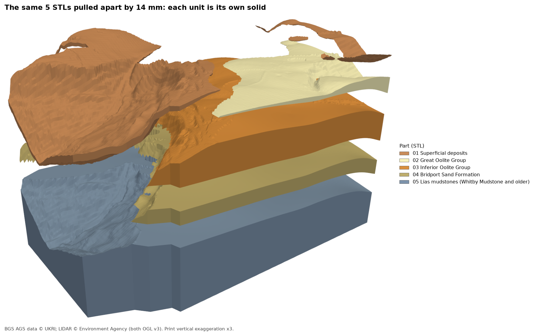
=== Step 4: cumulative solids and booleans ===whole model 197.9 x 145.0 x 71.4 mm, including the 3 mm plinthSUP 4 separate piece(s)GOG 1 separate piece(s)IOG 1 separate piece(s)BDS 1 separate piece(s)LIAS 1 separate piece(s)The superficial deposits are in four pieces: the large spread on the scarp slope, a strip along the north-eastern edge of the plateau and two small patches on it. All four are real deposits thicker than 1.89 m.
Step 5: check every part before writing
Nothing is written until every part passes. check_mesh counts edges: in a watertight mesh every edge is shared by exactly two triangles, and in a consistently oriented one each edge is used once in each direction. It also works out the volume from the triangles, which must be positive (a negative volume means the mesh is inside out):
def check_mesh(verts, tris): """Every edge shared by exactly two triangles, used once in each direction, and a positive volume.""" e = np.concatenate([tris[:, [0, 1]], tris[:, [1, 2]], tris[:, [2, 0]]]) n = len(verts) und = np.unique(np.sort(e, axis=1) @ np.array([n, 1]), return_counts=True)[1] drc = np.unique(e @ np.array([n, 1]), return_counts=True)[1] t = verts[tris] vol = np.einsum("ij,ij->i", t[:, 0], np.cross(t[:, 1], t[:, 2])).sum() / 6 return bool((und == 2).all()), bool((drc == 1).all()), volThen the parts are checked against each other. Their volumes must add up to the whole ground solid, and no two parts may share any volume. If either test fails, the script stops:
total, whole = sum(m[2] for m in meshes.values()), whole.volume()overlap = sum((solids[a] ^ solids[b]).volume() for i, a in enumerate(codes) for b in codes[i + 1:])if abs(total - whole) > 0.001 * whole or overlap > 0.001 * whole: raise RuntimeError("the parts do not add up to the ground solid")=== Step 5: check every part before writing ===sum of parts 1450.952 cm3 | ground solid 1450.952 cm3 | difference +0.0000% | pairwise overlap 0.0000 mm3The parts fill the model exactly, with nothing missing and nothing printed twice.
Step 6: one STL per unit and a colour 3MF
Each part is written as a binary STL with the structured-dtype writer from DEM to STL, numbered from the top down so they sort in order in the slicer. All five also go into one 3MF, with the unit names and the same colours as Part 5’s figures:
=== Step 6: write one STL per unit and a colour 3MF ===file unit triangles cm3 PLA g watertight01_SUP.stl Superficial deposits 46,676 35.62 44.2 True02_GOG.stl Great Oolite Group 24,120 23.63 29.3 True03_IOG.stl Inferior Oolite Group 72,058 305.67 379.0 True04_BDS.stl Bridport Sand Formation 76,698 172.61 214.0 True05_LIAS.stl Lias mudstones (Whitby Mudstone and older) 93,058 913.43 1132.6 Truetotal 312,610 1450.95 1799.2 (solid PLA; at 15% infill a slicer will use much less)ground_model.3mf 2.9 MB | 5 parts: Superficial deposits, Great Oolite Group, Inferior Oolite Group, Bridport Sand Formation, Lias mudstones (Whitby Mudstone and older)The volumes are for solid parts. With two or three walls and 15% infill, the Lias block uses a fraction of its 1.1 kg, and the thin upper parts are mostly wall anyway. If you want to save more, raise the model base in Part 5: everything below the lowest surface, 127.8 m OD, is plain Lias plinth.
Step 7: previews from the STL files
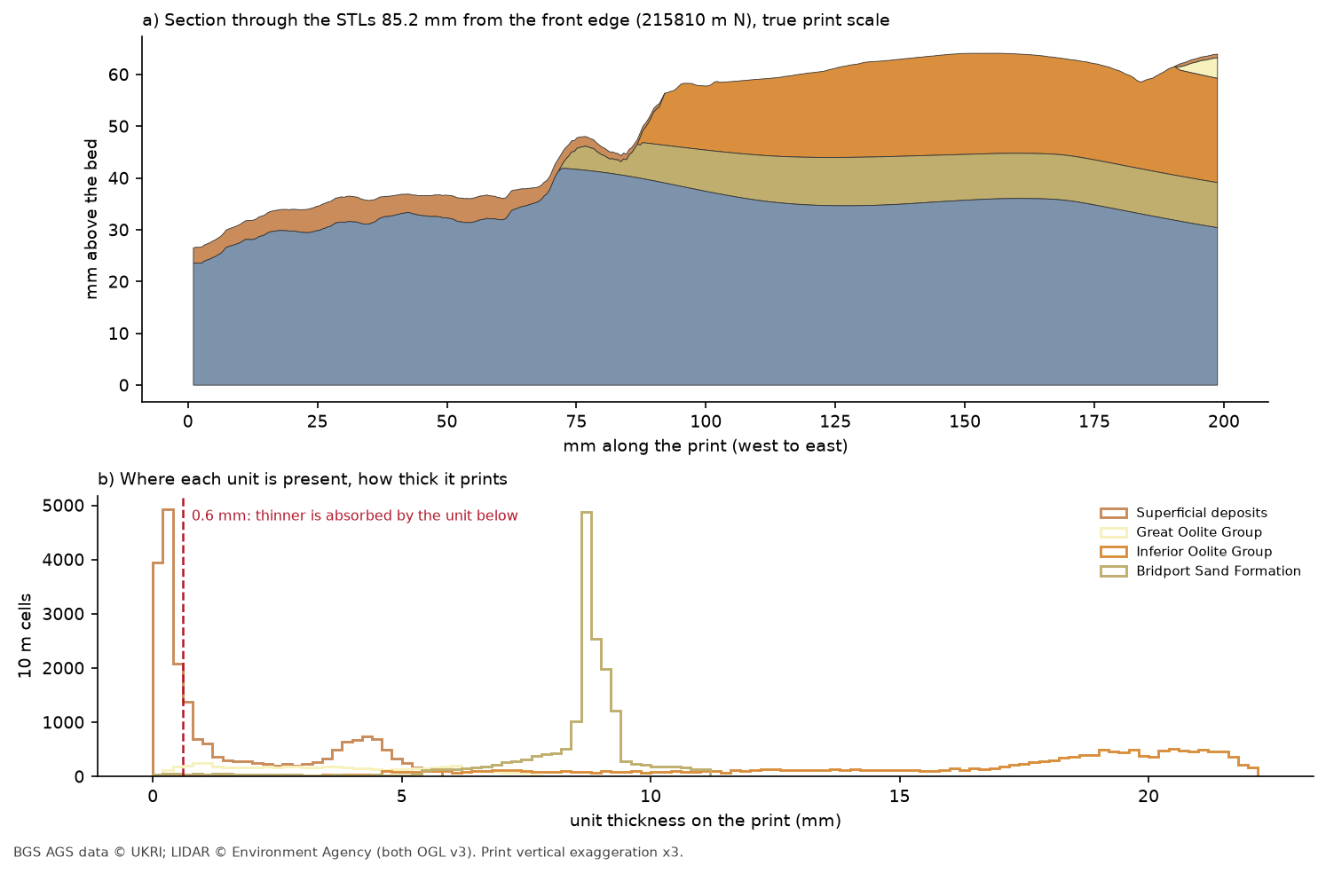
Every picture in this post is rendered from the STL files read back from disk with pv.read, not from the arrays in memory. If the files were wrong, the pictures would be too. The section in figure 3 is cut through the STL meshes with manifold3d’s slice.
=== Step 7: previews rendered from the STL files ===read back 5 STLs: 197.9 x 145.0 x 71.4 mmfigures written: 01-printable-ground-model.png, 02-exploded-view.png, 03-print-layers-section.png, 04-slicer-style-top.pngfinished in 6.9 s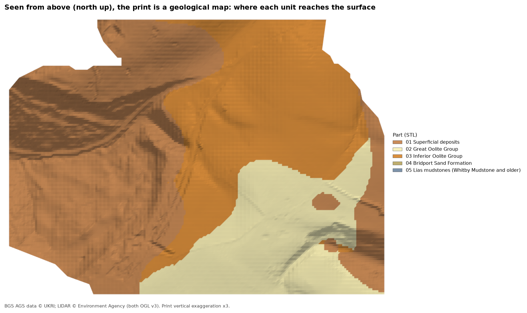
Printing tips
- Loading the parts: drag all five STLs into PrusaSlicer, Bambu Studio or OrcaSlicer together and accept the offer to load them as one object with multiple parts, so they stay aligned. Or open
ground_model.3mf, which keeps the names and positions. Then give each part its filament. - Colours: follow the geological map if you can: a brown or tan for superficial deposits, cream for the Great Oolite, orange for the Inferior Oolite, olive or khaki for the Bridport Sand and a slate blue-grey for the Lias. What matters most is that neighbouring units contrast.
- Layer height: 0.2 mm suits the 0.6 mm rule. If you print at 0.12 mm, you could lower
MIN_MMto about 0.4 mm. - Purge: the Lias block is large, so use “flush into infill” to absorb most of the purge from the colour changes.
- Single extruder: the units are not flat bands, so a filament change at one height will not reproduce them. Print the Lias block and the upper parts separately and glue them, or print in one colour and paint the side walls.
Frequently asked questions
How do I 3D print a geological model?
Build one surface per geological contact, for example by kriging borehole picks as in Part 5. Turn each surface into a heightfield solid from a flat base, subtract the solid below to get each unit, check that every part is watertight and that they add up to the whole, and write one STL per unit. Load the STLs into your slicer as parts of one object and give each unit its own filament.
Why do the units go all the way through, instead of just colouring the surface?
Because the side walls are the most useful part of a geological print: they are cross-sections. Solid units also make the print robust, and you can cut it with a saw along any line to show a section, as figure 3 does on screen.
What vertical exaggeration should I use for a geological print?
Enough that the thinnest unit you care about is at least three or four print layers thick, without turning slopes into cliffs. Three times suits this site: the Bridport Sand, mostly about 28 m thick, prints at about 8.7 mm (figure 3b), half the superficial deposits’ area survives, and it matches the 3D views in Parts 3 and 5. More would keep more superficial deposits but would make the scarp look far steeper than it is.
Can I print the model at a larger size?
Yes. Change LONG_MM. At 250 mm the scale is about 1:7,600, a 10 m cell is 1.3 mm and, at three times exaggeration, 0.6 mm is 1.5 m of strata. For anything bigger than your print bed, the tiling tutorial cuts a model into jigsaw tiles, and the same cut works on each unit.
Why does the script check the parts when manifold3d already makes valid meshes?
Because the check is cheap and the print is expensive. The edge and volume checks catch an inside-out part or a gap at once, and the sum and overlap checks catch a mistake in the stack that would leave two parts claiming the same space.
Next steps
- Back to Part 5: the ground model, to change the surfaces or extend the model before printing.
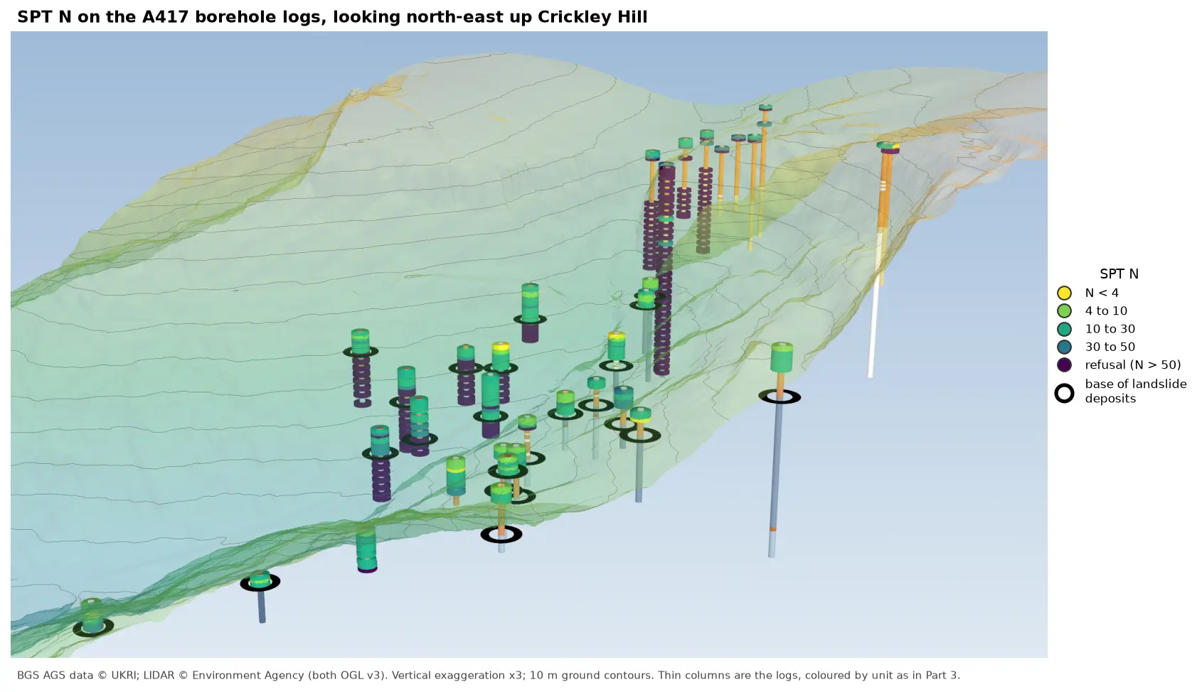
- Part 6: SPT N-values adds the test results, showing which of the printed units are soft and which refuse.
- Multi-colour 3D-printed terrain explains the one-solid-per-colour approach in more detail, including thin colour caps that save filament.
- From DEM to 3D-printable STL starts the 3D-printed maps series from the beginning, with the heightfield solid and the STL writer used here.
- Tiling a large 3D-printed terrain model for a model of the whole A417 route.
Data and licences
- A417 Missing Link ground investigation (BGS deposited data items 173984 and 173975; client Highways England, now National Highways), downloaded through the BGS AGS borehole index and export APIs in Part 5. Contains British Geological Survey materials © UKRI 2026, licensed under the Open Government Licence v3.0.
- Environment Agency LIDAR Composite DTM 1 m, the top surface of the model, from the Defra Data Services Platform WCS. © Environment Agency copyright and/or database right, licensed under the Open Government Licence v3.0. Every figure carries the credit.
- Code:
print_ground_model.py, tested with Python 3.12.0, numpy 2.5.4, rasterio 1.5.2, shapely 2.2.0, manifold3d 3.5.5 and pyvista 0.49.2. It runs entirely offline on Part 5’s output.
Key terms
- Heightfield solid
- A closed mesh made from a grid of heights: a top surface, a flat bottom and walls around the edge. Each unit here is the difference between two of them.
- Watertight
- A mesh with no holes: every edge is shared by exactly two triangles. Slicers need watertight parts to know what is inside.
- 3MF
- A zipped 3D printing format that keeps several named parts together, in position and with colours, in one file.
- Vertical exaggeration
- Stretching heights relative to horizontal distances so that relief and thin layers show at small scales. Here heights are tripled.
Data for this tutorial
- BGS AGS borehole data · Donated AGS ground investigation data, Open Government Licence
- GIS data sources for the United Kingdom · Including Environment Agency LIDAR, Open Government Licence
Licences and formats for each source are listed in the GIS data sources catalogue.